ElectroSlide® – Powered Flow Control
Jacopa offers a range ElectroSlide® powered flow regulators suitable for use within foul and surface water systems. The system is controlled through a plc programme that calculates the required orifice open area by monitoring the upstream water head.
| Specification: | |
| Sizes | From DN 150 to DN 1500 |
| Flow Rates | From 3 l/s to 6,100 l/s per unit. |
| Actuator | Rotork / Auma to suit client requirement. |
| Material | Stainless Steel grade 304 or 316L |
| Downloads | |
ElectroSlide® – Key Features & Benefits:
- Sizes from 150 mm dia to 1500 mm dia available
- Can be used for both foul and Surface Water systems
- Real time control of flows
- Automatic blockage release ability
- Up to 5 variable flow rates programmable
How the ElectroSlide® Creates Value
- Assists in preventing property flooding
- Minimises upstream storage requirements
- Complex regulation patterns can be programmed as required, via plc control
- Can be set to regulate flows based upon downstream hydraulic conditions
- Actuator fitted to slide mounting for easy maintenance
Equipment Supplied
The following equipment can be supplied by Jacopa as part or whole of the complete package.
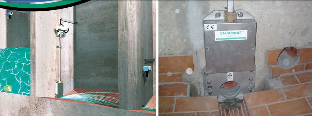
- ElectroSlide® unit with drive shaft.
- Auma or Rotork actuator to suit unit. 3 Phase EX rated for hazardous areas. A single-phase motor is available, but cannot be used in a hazardous area as EX rating is not available.
- Ultrasonic level controller (Pulsar or Siemens)
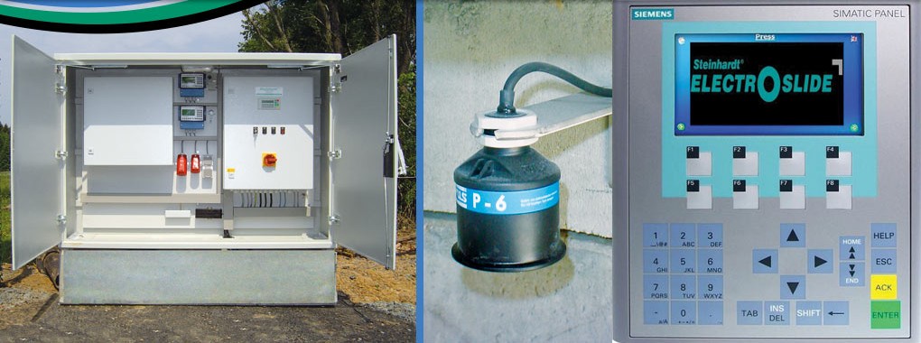
- Plc / HMI with control programme.
- Control Panel, pre-installed within a GRP or steel kiosk if required for quicker site installation
ElectroSlide® – Powered Flow Control
The downstream transducer monitors the regulated flow passing down the sewer. If this transducer does not register flow passing, and it is aware of the upstream level, it will assume that a blockage has occurred and will signal the ElectroSlide® to open in stages until flow is registered (blockage released); after which the control immediately reverts back to the controlling flow.
ElectroSlide® – Control Methods
Method 1 – Standard Sewer Installation
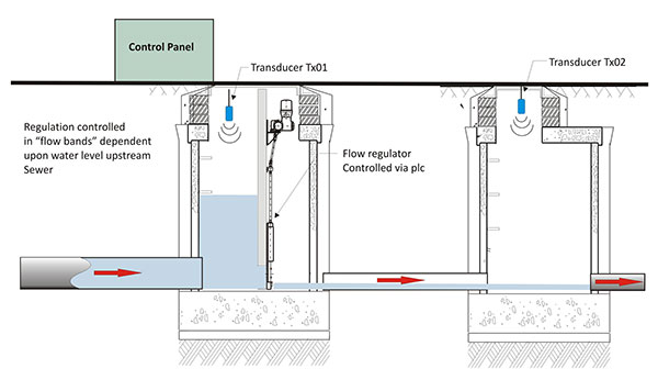
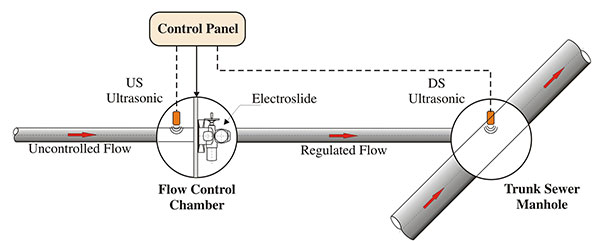
The schematic is for the installation of an ElectroSlide® within a sewer system, where two ultrasonic transducers are used. The upstream transducer views the flow level and regulates the aperture of the ElectroSlide® to suit the desired downstream flow rate. The flow is regulated by the plc which contains the head / discharge relationship calculation within its programme, and adjusts the open area of the ElectroSlide® body accordingly.

Method 2 – Utilising Downstream Flume
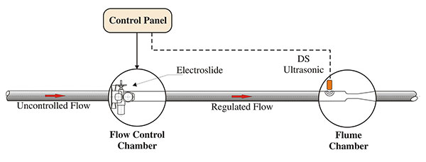
If it is possible to construct a flume in a downstream position from the point of control, then a single ultrasonic transducer can be used to control the flow.
Control is achieved within the ultrasonic controller using its flow control algorithm which compares the measured flow rate against the desired flow set-point. If the measured flow is below the desired set-point the penstock shall open in repeated successive fixed step movements (opening by a fixed step every 2 minutes for example) until the flow set-point is achieved. If the flow is above the set-point, the reverse will occur and the penstock shall close in successive fixed steps until the set-point is achieved.
The frequency and magnitude of step movements is adjustable from the ultrasonic controller during commissioning and determine the precision and speed of reaction in attaining the correct flow rate.
Method 3 – Utilising Upstream Transducer Only
It is possible to provide the flow control by monitoring the upstream water level only. The removal of the downstream level monitoring only effects the blockage release method.
As the downstream level cannot be monitored, the plc control programme allows for an upstream level to be input that when reached will permit the ElectroSlide® to be driven open to a defined aperture, then close back to regulating position. This function can be repeated at aninput time frequency whilst the upstream level is high. This routine ensures that a blockage is not responsible for the high upstream level.
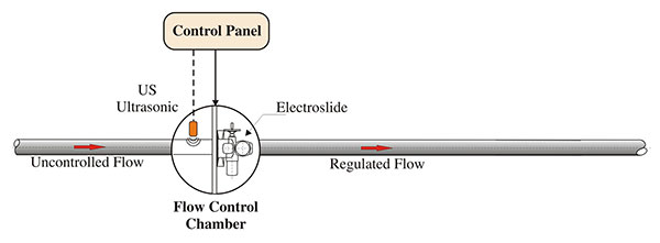
Method 4 – Regulating flows from a sub-catchment into a Trunk Sewer
This is similar to Method 1, but instead of monitoring the immediate downstream sewer, the ultrasonic is mounted in a nearby trunk sewer etc. This downstream transducer monitors the level within the trunk sewer and the ElectroSlide® flow rate is controlled relative to the downstream level. In this case, the blockage release function is controlled as method 3. Up to 5 flow bands can be programmed into the plc.
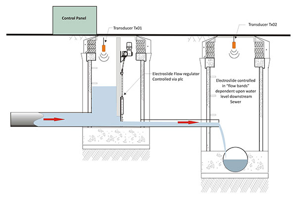
This type of system can be utilised to control discharges from attenuation structures (delaying dams) into a nearby watercourse. On occasion, a development can be consented to discharge surface water into a river at a flow rate dependent upon the level of the river; a similar control can be applied as above.


